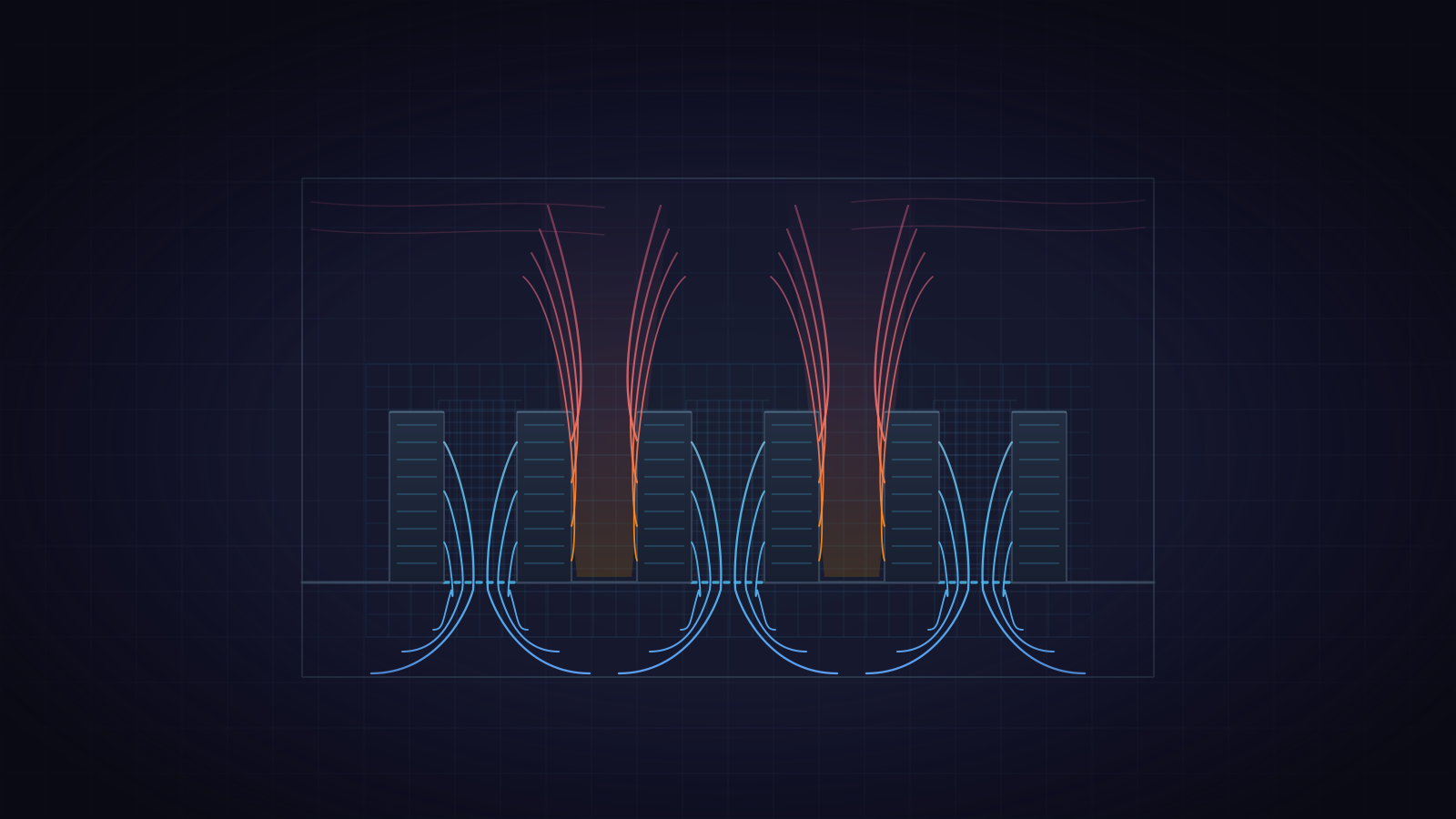
Computational fluid dynamics (CFD) computes how air, heat and pressure move through a space by solving the equations of fluid flow on a computer. For a data center, that turns questions like Will this row run hot if a cooling unit fails? or How much of our cooling is reaching the racks? into questions you can ask of a model instead of the room.
The governing equations
Fluid flow is governed by three conservation laws: mass cannot appear or disappear, force equals the rate of change of momentum, and energy is conserved. Together they are usually called the Navier–Stokes equations.
Conservation of mass says that air flowing into any small volume either flows out again or changes the density \( \rho \) inside it, where \( \mathbf{u} \) is the air velocity:
\[ \frac{\partial \rho}{\partial t} + \nabla \cdot (\rho\,\mathbf{u}) = 0 \]Conservation of momentum relates the air’s acceleration to pressure gradients, viscous friction, and body forces \( \mathbf{f} \):
\[ \rho\left(\frac{\partial \mathbf{u}}{\partial t} + \mathbf{u}\cdot\nabla\mathbf{u}\right) = -\nabla p + \mu\,\nabla^2 \mathbf{u} + \mathbf{f} \]In a data center the body force that matters is buoyancy. Air in a data hall moves too slowly for pressure to change its density noticeably, but temperature does, and that is why rack exhaust rises toward the ceiling. CoolSim computes density from temperature with the ideal gas law, at the air pressure for the site’s altitude, so warm air rises in the model as it does in the room.
Cooling is about moving heat, so an energy equation tracks temperature \( T \) as the flow carries it and the air conducts it:
\[ \rho\,c_p\left(\frac{\partial T}{\partial t} + \mathbf{u}\cdot\nabla T\right) = \nabla \cdot (k\,\nabla T) + S \]where \( S \) is the heat added, for example by the equipment in a rack.
There is no closed-form solution to these equations for a real room full of racks, ducts and obstructions, so they are solved numerically.
CoolSim solves the steady form: the time derivatives are set to zero, and the answer is the state the room settles into with its heat loads and cooling held fixed. That answers where the air and heat end up. How quickly a room heats up after a failure is a different question. It needs a transient (time-dependent) calculation, which we run as a separate thermal-failure study.
How a simulation works
Every CFD study follows the same four steps.
- Define the domain. Build the geometry and set the boundary conditions. For a data hall that means the room, the raised floor or ceiling plenum, racks with their heat loads and airflows, cooling units with their supply temperatures and airflow, perforated tiles, and any containment.
- Mesh it. Divide the space into many small cells. The equations are approximated on each cell, which turns calculus into a large system of algebraic equations. Finer meshes capture more detail at the cost of more computation. CoolSim builds the mesh from the model when the job is submitted.
- Solve. The solver iterates until the mass, momentum and energy balances hold in every cell and the quantities being watched stop changing.
- Post-process. The solution becomes something you can act on: temperature and velocity maps, pathlines showing where the supply air goes, rack intake temperatures, and metrics built from them.
Turbulence
Air in a data hall is turbulent. The smallest eddies are far smaller than any practical cell, so turbulence is modeled rather than resolved. Its main effect is faster mixing of momentum and heat, and models represent that as an added, turbulent viscosity.
General-purpose CFD codes often compute that viscosity from two extra transport equations, the k-ε and k-ω families. CoolSim uses a simpler zero-equation, or mixing-length, model. It computes the turbulent viscosity directly from the local flow and the distance to the nearest wall, with no extra equations to solve. Zero-equation models are a common choice for enclosed rooms such as data centers, where the questions are about where air goes at the scale of racks and aisles.
Convergence
A converged solution means the equations are balanced on this mesh. It does not mean the inputs are right. A model is only as good as its rack heat loads and airflows, its cooling-unit settings, and the leakage paths it includes. For that reason, the difference between two runs of the same model (with and without containment, with one cooling unit off) is usually more trustworthy than any one absolute temperature.
Why CFD fits data center cooling
Data center cooling is a spatial problem. A room can have more total cooling capacity than its heat load and still overheat a rack, because the cold air never reaches that rack’s intake. Averages don’t show that; a spatially resolved model does. CFD lets a team:
- find hot spots and trace them to their cause, such as recirculated exhaust, a starved tile or bypass air;
- check whether the room could run with less cooling airflow or a warmer supply, which is where PUE improvements usually come from;
- run failure cases, such as each cooling unit off in turn, on the model instead of the room; and
- compare options such as containment, plenum depth or tile layout before committing capital.
Where CoolSim fits
Traditionally, CFD meant general-purpose software and a dedicated analyst. CoolSim packages the workflow for data centers. Models are built in a Windows application from libraries of racks, cooling units, tiles and other data center objects. The meshing and the Ansys Fluent solve run in the cloud, and the results come back as a report with rack intake temperatures, maps, pathlines and the RCI and RTI cooling metrics.
For a longer introduction, with two example rooms, see WP107: Using CFD for Data Center Design and Analysis.