Introduction
Many data center operators now face the same request: put a row of AI servers into a room that was built for ordinary IT equipment. The numbers are hard to ignore. NVIDIA gives about 120 kW for one of its GB200 NVL72 racks [2], thirty times the 4 kW of each rack in the room studied here. Racks this dense are built for liquid cooling. Cold plates carry most of the heat away from the processors in water, while the rest of the rack (memory, power supplies, network cards) is still cooled by room air. How much stays on air depends on the hardware.
Even the part that stays on air is large. If liquid takes 80% of a 120 kW rack’s heat, the rack still puts 24 kW into the room. That is six times a 4 kW rack, and above the roughly 20 kW per rack that Schneider Electric gives as what air cooling can support with hot aisle containment [3].
So the question for the operator is not only whether the chillers can carry the extra load, but where the air-side heat goes and what it does to the racks that were already there. That is a question about airflow, which is what computational fluid dynamics (CFD) is for. In this paper, CoolSim is used to add a row of eight AI racks to an existing 7,100 sq.ft. air-cooled room. CoolSim models the room air, not the liquid loop, so each AI rack is given the heat it puts into the room: 12, 24 or 36 kW, which is what a 120 kW rack leaves on air if liquid takes 90, 80 or 70% of its heat. Two positions for the new row are also tested.
Problem Description
The room (Figure 1) is 124 ft by 57.5 ft, with a slab floor, an 11.75 ft ceiling and a 21 in. plenum above the ceiling. It holds 234 racks at 4 kW each, 936 kW in total, in 14 rows of 16 or 17 racks. The rows form seven hot aisle pairs. Each hot aisle is enclosed, and its exhaust leaves through grilles into the ceiling plenum. Four building columns stand in the rows, and a block of structure runs along part of one long wall.
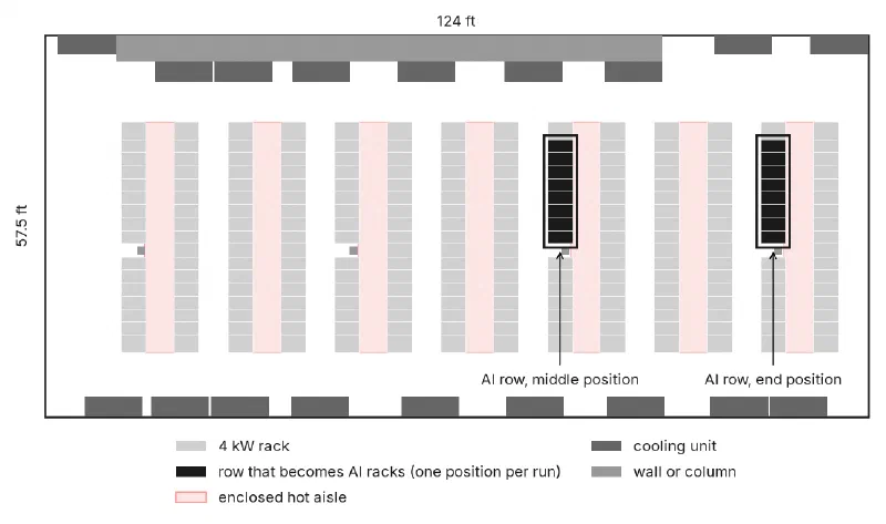
Figure 1
Plan view of the room: 234 racks (light gray) in seven enclosed hot aisle pairs (pale red), 18 cooling units (dark gray) on the long walls, and the two positions tested for the AI row (black, one position per case)
Eighteen cooling units along the two long walls supply about 6,500 CFM each, 117,000 CFM in total. Seventeen supply 60°F air and one supplies 65°F. Each 4 kW rack draws about 490 CFM, enough to keep its exhaust about 25°F warmer than its inlet. Together the racks draw about 114,300 CFM, 98% of what the cooling units supply.
As built, the room works well. Every rack is within the ASHRAE recommended range, and the hottest rack inlet in the room is about 77°F.
The AI Row
Eight racks, the half of one 16-rack row on one side of a building column, are replaced by AI racks rated at 120 kW each. Those eight racks carry 960 kW, more than the other 226 racks in the room combined (904 kW), but most of it leaves by liquid and never reaches the room air. Nothing else in the room changes: the same cooling units, the same supply temperatures, the same containment.
Only the heat that reaches room air is modeled. Three cases were tested, named by the heat each AI rack puts into the room: the 12 kW, 24 kW and 36 kW cases. The AI racks are assumed to run the same 25°F temperature rise as the existing racks, so the air each one draws grows with the heat it sends to air (Table 1).
| Case | Heat to air, per AI rack | Air drawn, per AI rack | Heat to air, whole room | Air drawn by all racks, as % of cooling unit supply |
|---|---|---|---|---|
| Room as built (4 kW racks) | 4 kW | 490 CFM | 936 kW | 98% |
| 12 kW AI row | 12 kW | 1,460 CFM | 1,000 kW | 104% |
| 24 kW AI row | 24 kW | 2,930 CFM | 1,096 kW | 114% |
| 36 kW AI row | 36 kW | 4,390 CFM | 1,192 kW | 124% |
Table 1
What the AI row puts into room air in each case
The last column is the one to watch. As built, the racks draw slightly less air than the cooling units supply. With the AI row in place, they draw more: 4% more in the 12 kW case, 24% more in the 36 kW case.
Two positions were tested for the row: in the second-to-last row near the end wall (the end position), and in the ninth of the 14 rows (the middle position).
How the Room Was Modeled
The room was built and solved with CoolSim’s standard model setup, the same one used for customer jobs, and each case had to pass the same convergence checks before results were taken. The AI racks are ordinary racks in the model, each entered with its full 120 kW and the share of it that goes to liquid; Checking the Liquid Split, below, shows how that heat is accounted for. The cooling units in the model always supply air at their set temperature, whatever the load. What that leaves out is covered below, under What the Model Does Not Include.
Each rack is judged by the hottest point on its inlet face, against the ASHRAE limits for class A1 equipment [1]: recommended up to 80.6°F, allowable up to 89.6°F.
A solved room of this size never sits perfectly still. Individual rack readings keep moving by a few degrees from one iteration to the next, so a rack close to a limit can be over it in one snapshot and under it in the next. Each case was therefore sampled 20 times, 25 iterations apart, and the counts below are given as the range over those 20 snapshots.
Results
Table 2 summarizes all seven cases. As built, no rack is over the recommended limit. In the 36 kW case, 59 to 66 of the 234 racks are over recommended and 10 to 14 are over allowable, depending on the snapshot and the row’s position. In the 24 kW case the counts fall to 35 to 42 and 2 to 3. In the 12 kW case, no rack is over allowable, but 7 to 13 are still over recommended.
| Case | Racks over recommended | Racks over allowable | Hottest rack inlet (°F) |
|---|---|---|---|
| Room as built | 0 | 0 | 76.6–77.7 |
| 12 kW, end | 9–13 | 0 | 85.3–85.8 |
| 12 kW, middle | 7–12 | 0 | 83.3–83.7 |
| 24 kW, end | 35–42 | 2–3 | 89.8–90.2 |
| 24 kW, middle | 35–41 | 2–3 | 90.1–90.8 |
| 36 kW, end | 61–65 | 10–12 | 92.9–93.1 |
| 36 kW, middle | 59–66 | 12–14 | 94.2–94.6 |
Table 2
Racks (of 234) whose hottest inlet reading is over the ASHRAE recommended (80.6°F) or allowable (89.6°F) limit, and the hottest rack inlet in the room. Ranges are over 20 snapshots of each solved case
The more telling result is where the hot racks are (Figure 2). They are mostly not in the AI row. In the 36 kW case with the row at the end position, all 11 racks shown over the allowable limit are ordinary 4 kW racks: 5 in the row that shares the AI row’s cold aisle, and 6 in the row that shares its hot aisle. The eight AI racks themselves read between 74.5 and 87.7°F, and none is over allowable. Racks over the recommended limit show up in 8 of the room’s 14 rows, from just short of the middle of the room to the end wall.
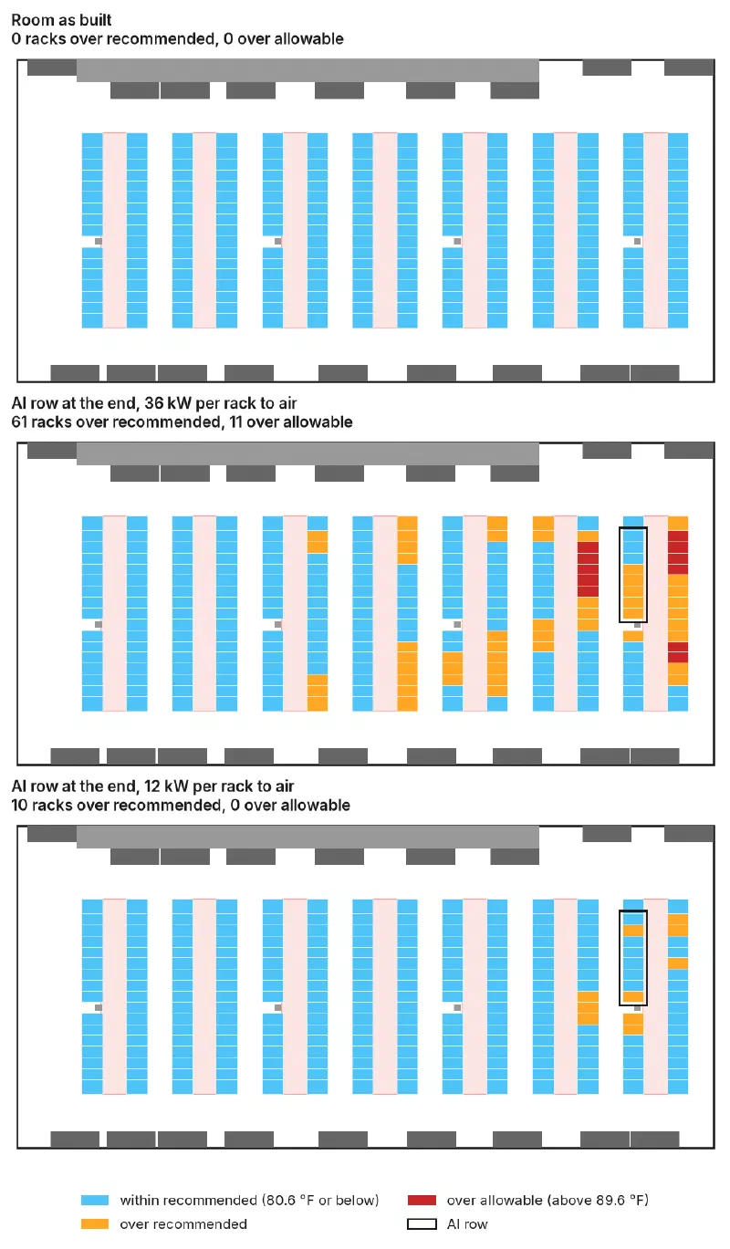
Figure 2
Each rack colored by its hottest inlet reading (median of 20 snapshots): the room as built (top), with the AI row at the end position putting 36 kW per rack into room air (middle), and 12 kW per rack (bottom)
Where the Row Goes
Figure 3 compares the two positions in the 24 kW case. The affected racks are different, clustered toward the end wall in one case and around the middle rows in the other, but the counts are the same: 35 to 42 racks over recommended with the row at the end, 35 to 41 with it in the middle, and 2 to 3 over allowable either way. In the 36 kW case the middle position is slightly worse (12 to 14 racks over allowable against 10 to 12), and in the 12 kW case it is slightly better (7 to 12 over recommended against 9 to 13).
In this room, moving the AI row moves the problem around. It does not make it smaller.
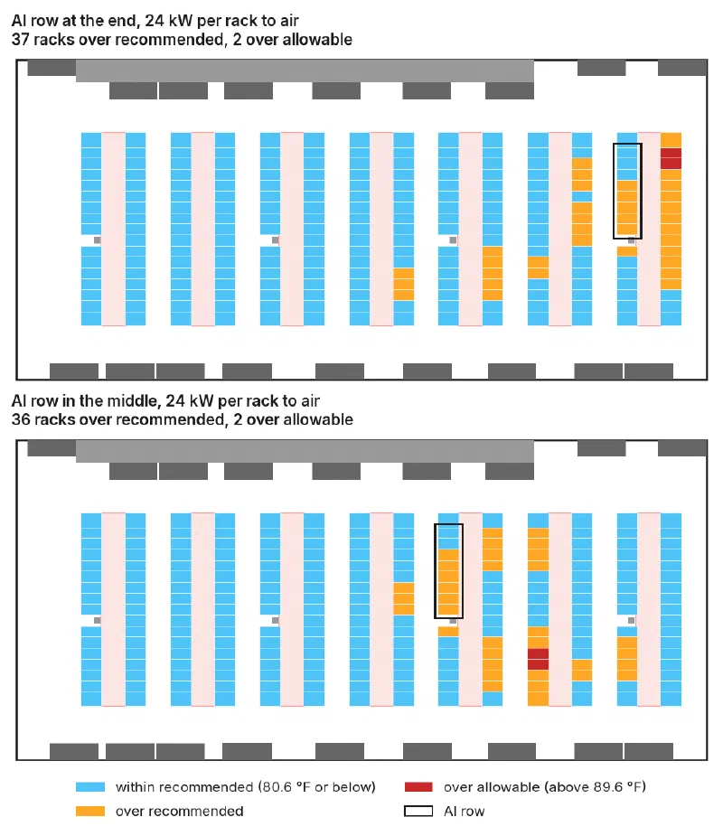
Figure 3
The AI row at the end position (top) and the middle position (bottom), both at 24 kW per rack to room air
Why: The Air Balance
Figure 4 plots the number of racks over each limit against the air all racks draw, as a share of what the cooling units supply. Both counts climb with it. Over-recommended racks go from none at 98%, to 7 to 13 at 104%, 35 to 42 at 114% and 59 to 66 at 124%.
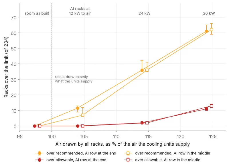
Figure 4
Racks over each limit against the air drawn by all racks, as a share of cooling unit supply. Markers show the median of 20 snapshots, bars the range
The reason is bookkeeping. A rack takes in as much air as its fans move, whether or not the cooling units supply that much. When the racks together draw more than the units supply, the difference has to come from air that has already been through a rack. At 124%, nearly a fifth of the air entering the racks is exhaust, even with every hot aisle enclosed. Because the cooling units in the model always supply air at their set temperature, every rack that runs hot in these results is running hot because it is taking in exhaust.
This is also why even the 12 kW case puts racks over the limit. At 12 kW to air, each AI rack still draws about 1,460 CFM, three times an ordinary rack, and the room as a whole draws 4% more air than the units supply. Twelve kilowatts is well under the 20 kW per rack guideline, but the room started with only 2% of spare airflow, and the AI row used all of it.
The room total is a warning sign, not a verdict. It says the racks as a whole are short of air; it does not say which racks go short, or how many. A companion paper, WP111, switches off one cooling unit at a time in this same room. With any one unit off, the racks draw 103% of what the other 17 supply, close to the 104% of the 12 kW case here, yet the result runs from no rack over the recommended limit to 18, depending on which unit is off. Moving the AI row changed which racks crossed the line but not how many; switching off a different cooling unit changed how many.
Checking the Liquid Split
Each AI rack was given what a CoolSim user gives any liquid-cooled rack: its full power, and the share of that power its cold plates carry away in liquid. CoolSim takes the liquid share out of the room. The rest goes into the rack’s exhaust air, and the rack’s airflow follows from that heat and its temperature rise. The liquid itself is not modeled, so in the model the heat that goes to liquid simply leaves the room. That is the right picture for direct-to-chip cooling, where the coolant loop takes the cold plates’ heat out of the room to the building’s cooling water.
This gives a check that can be made on every solved case. The heat the cooling units take out of the room air should equal the rack power less the liquid share: no more, because the liquid share has left, and no less, because everything left on air has to reach a cooling unit. Table 3 makes that comparison for all seven cases.
| Case | Rack power, whole room | To liquid | Left in room air | Removed by cooling units |
|---|---|---|---|---|
| Room as built | 936 kW | 0 | 936 kW | 937 kW |
| 12 kW, end | 1,864 kW | 864 kW | 1,000 kW | 1,001 kW |
| 12 kW, middle | 1,864 kW | 864 kW | 1,000 kW | 1,002 kW |
| 24 kW, end | 1,864 kW | 768 kW | 1,096 kW | 1,097 kW |
| 24 kW, middle | 1,864 kW | 768 kW | 1,096 kW | 1,097 kW |
| 36 kW, end | 1,864 kW | 672 kW | 1,192 kW | 1,193 kW |
| 36 kW, middle | 1,864 kW | 672 kW | 1,192 kW | 1,193 kW |
Table 3
Where the rack heat goes in each case. The last column is the heat removed by all cooling units, from each solved case’s CoolSim report
In every case the two agree to within 2 kW. The room as built, with no liquid at all, is out by 1 kW, and the 18 cases of WP111, also without liquid, by 0 to 2 kW, so the difference belongs to the solution rather than to the liquid split.
The seven cases had each rack’s heat set directly in the solver’s input. For a customer’s job, CoolSim sets it earlier: before the room is meshed, it reads each rack’s full power and liquid share and gives the rack the difference. To check that step as well, the 24 kW end case was also run as an ordinary CoolSim job. Each AI rack came out of it at 24 kW, and the solved report shows 1,096 kW removed by the cooling units against 1,096 kW left in the room air. The room as built, run the same way, shows 936 kW against 936 kW.
This is a check of the model’s bookkeeping, not of its accuracy. It shows that the heat sent to liquid leaves the room, and that the heat left on air is all carried to the cooling units, none lost and none counted twice. It does not show that the temperatures in this model match a real room with these racks in it; that would take measurements from one.
One point for anyone reading a CoolSim report for a room like this: the report’s total heat load, 1,864 kW here, includes the heat that leaves by liquid. The heat removed by the cooling units is the load the room air actually carries.
Not every kind of liquid cooling works this way. A rear-door heat exchanger cools the rack’s exhaust after the servers’ fans have moved it, so the rack still draws the air for its full load. Coolant distribution units that reject their heat into room air, rather than to building water, put the liquid’s heat back into the room. Neither arrangement is part of this study.
What the Model Does Not Include
- The liquid loop. CoolSim models the room air only. Cold plates, coolant distribution units and wherever they reject their heat are not modeled: each AI rack is given only the heat and airflow it puts into the room, and how a real rack splits its heat between liquid and air has to come from its vendor.
- Cooling unit capacity. The cooling units hold their supply temperature, which assumes their coils can absorb room air heat rising from 936 kW to between 1,000 and 1,192 kW. If they cannot, supply air warms up and every rack in the room runs hotter, so on this point the results are a best case.
- The AI racks’ real airflow. The AI racks are given the same 25°F rise as the existing racks. Hardware that runs a larger rise draws less air for the same heat and would upset the balance less. The vendor’s airflow figure at the planned load is worth having before modeling.
- Other rooms. These counts belong to this room and layout. The air balance is the part that carries over.
Conclusions
One row of eight AI racks was added to a 234-rack air-cooled room with enclosed hot aisles, at three levels of heat to air (12, 24 and 36 kW per AI rack) and two positions. The results suggest:
- Check the air balance before the heat. Add up the air the new racks will draw and compare the room’s total with what the cooling units supply. This room started at 98%, and every AI row case took it past 100% and put racks over the recommended limit. The total is a warning, not a verdict: where the shortfall lands decides how many racks cross the line, and which.
- Look for the problem in the existing racks. The AI row itself stayed mostly within limits. The ordinary racks around it, and some several rows away, did not.
- Heat to air is the strong lever; position is weak. Going from 36 to 12 kW per AI rack took the racks over allowable from 10 to 14 down to none. Moving the row from the end to the middle changed which racks were affected, not how many.
- 12 kW per AI rack was still too much here, because this room had no spare air. Closing the last 4%, with more cooling unit airflow or AI hardware that puts less heat into the room or draws less air, is the kind of change that can be tested in CoolSim before any hardware moves.
References
- ASHRAE Technical Committee 9.9, Thermal Guidelines for Data Processing Environments, 5th ed., ASHRAE, 2021.
- NVIDIA, “NVIDIA Blackwell Platform Boosts Water Efficiency by Over 300x,” NVIDIA Blog, April 2025.
- Avelar et al., “The AI Disruption: Challenges and Guidance for Data Center Design,” Schneider Electric White Paper 110, v1.1.